- First Name
- Tom
- Joined
- Aug 14, 2020
- Threads
- 5
- Messages
- 28
- Reaction score
- 53
- Location
- San Francisco
- Vehicle(s)
- '16 Ford Focus RS, '25 BadSquatch
- Your Bronco Model
- Badlands
- Thread starter
- #1
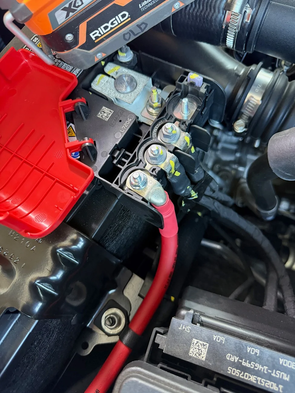
Despite putting an order in for a '21 Bronco, it took us until 2025 to actually pull the trigger on our Bronco Badlands w/ Lux and HOSS 3.0. This has given me LOTS of time to see what others have done on the forums and to generate an expensive wishlist of upgrades and best practices. After reading about @SierraBronco's near meltdown I had a strong desire to not do the same when it came time to add accessories. First addition to the new rig was a TrailRax and a light bar, followed by an ARB brushless twin. And for two of these, I needed power. I've been enamored with @EOS's SAPS system as well-engineered solution for modular, always-on power. And while I know that the upfitters are connected to relays I'm less thrilled with the current carrying capacity of the stock wiring, so I wanted to have a bit more flexibility / control.
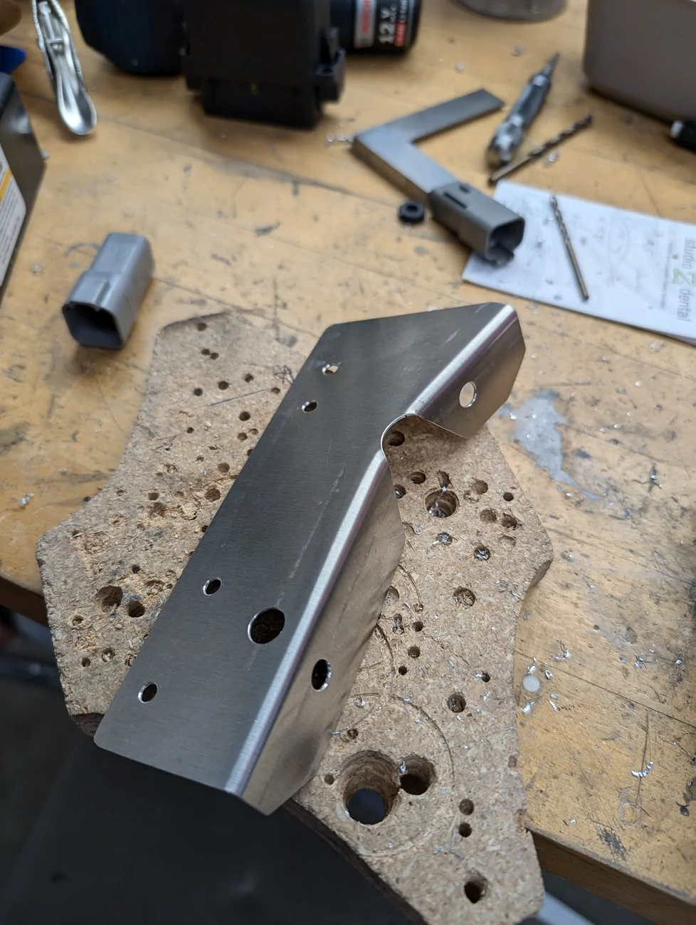
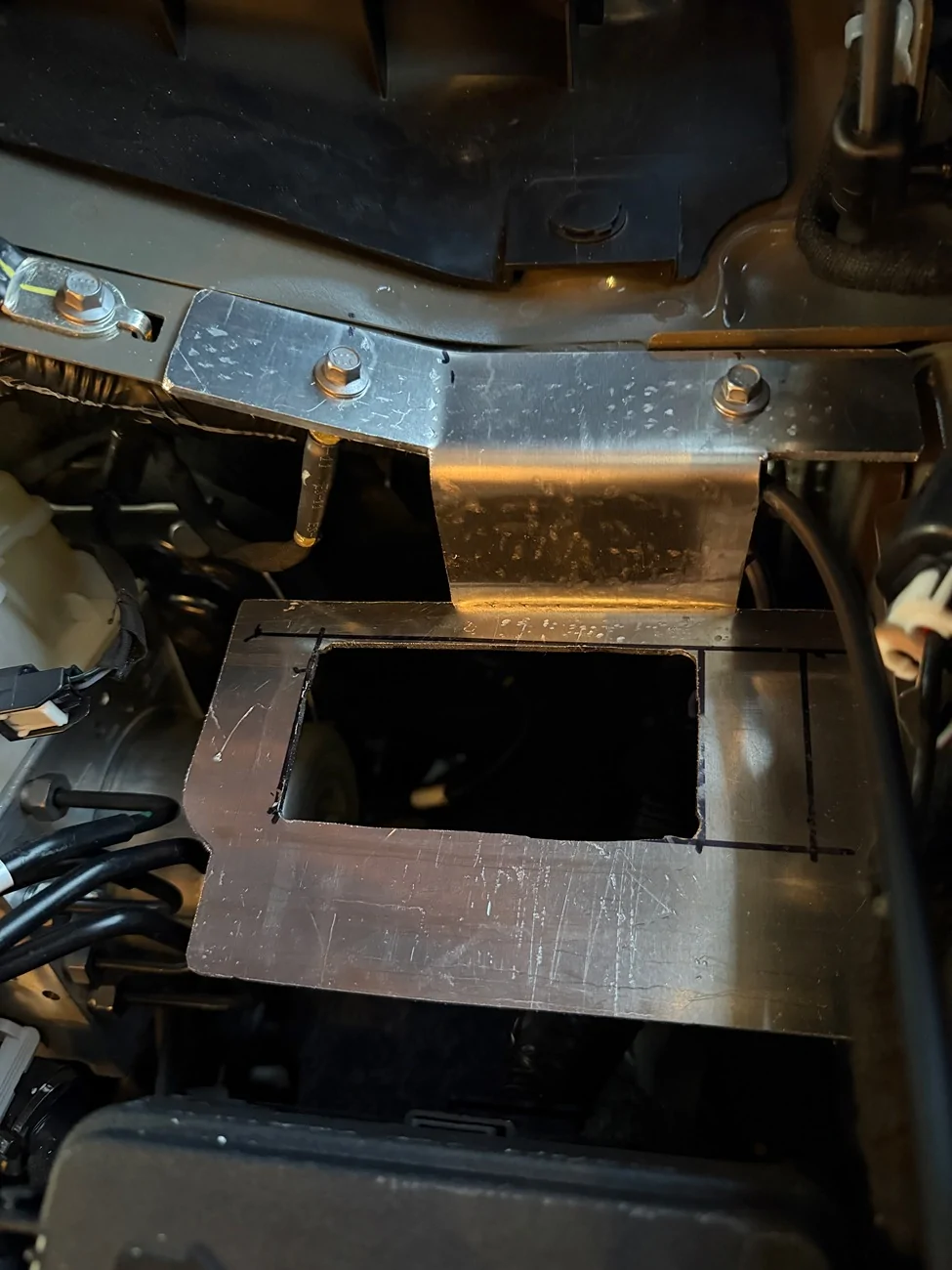
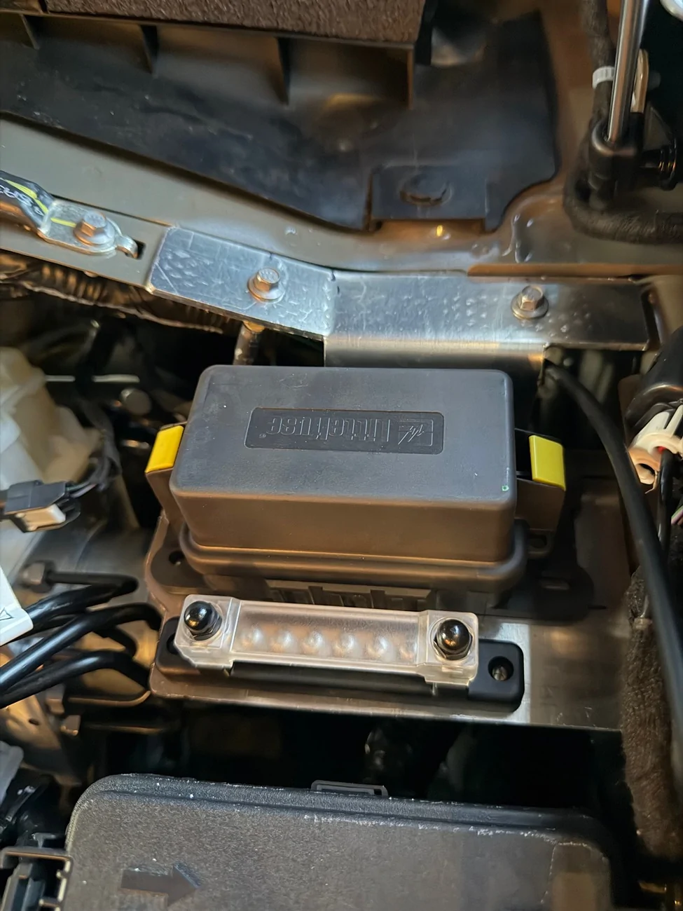
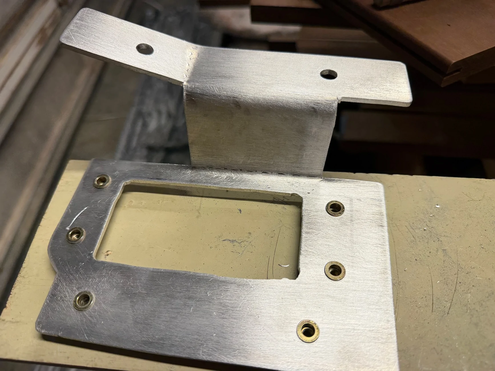
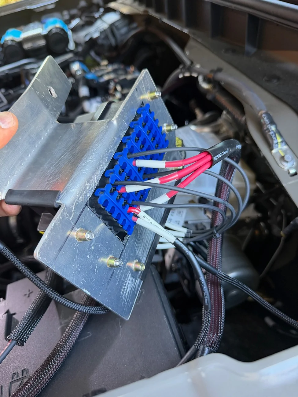
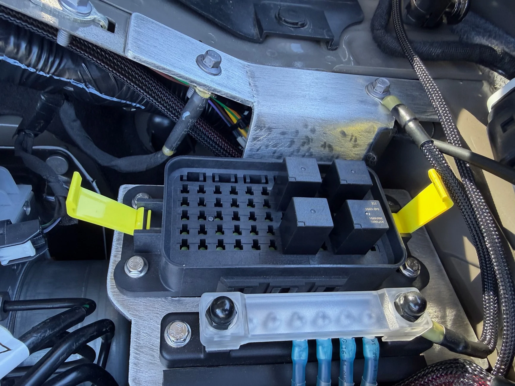
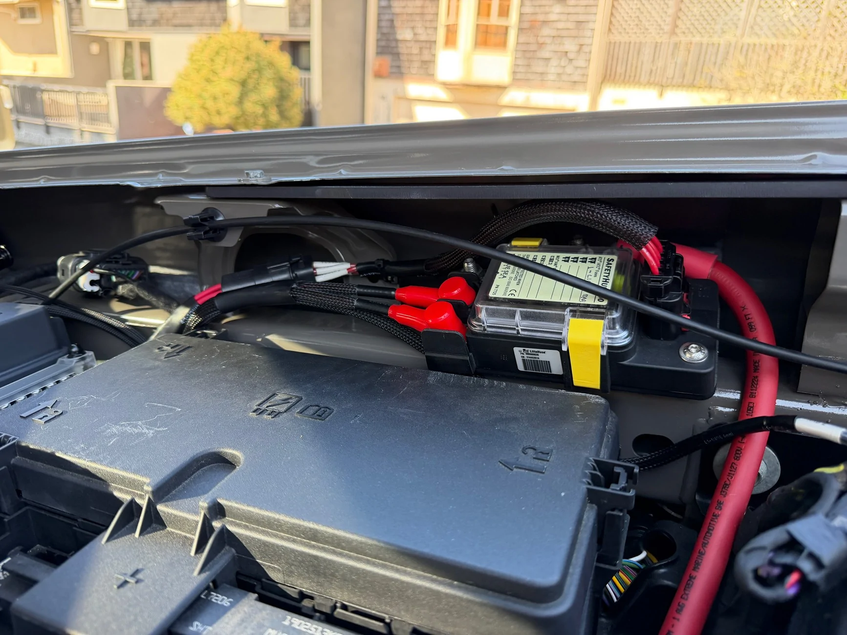
I decided to use the upfitters primarily as switches to control relays in a separate, modular power distribution box, with the SAPS supplying fused power. For the PDM, I opted for a Littelfuse PDM ($22 from Waytek). Provides a lot of space for relays and / or fuses, rated up to 250A of continuous current. Due to the size of the Metri-Pack 280 terminals each circuit is good for up to 30A. Mounting it near the SAPS and the upfitters required some creativity, though, since the hood struts cut into the available space. I ended up getting a piece of 1/8" 5052 aluminum and with the use of a jigsaw, hammer, and vise getting it into a reasonable shape. 90 degree bends were made perpendicular to the grain to prevent cracking. I used metric rivnuts to hold down the PDM and a ground bus.


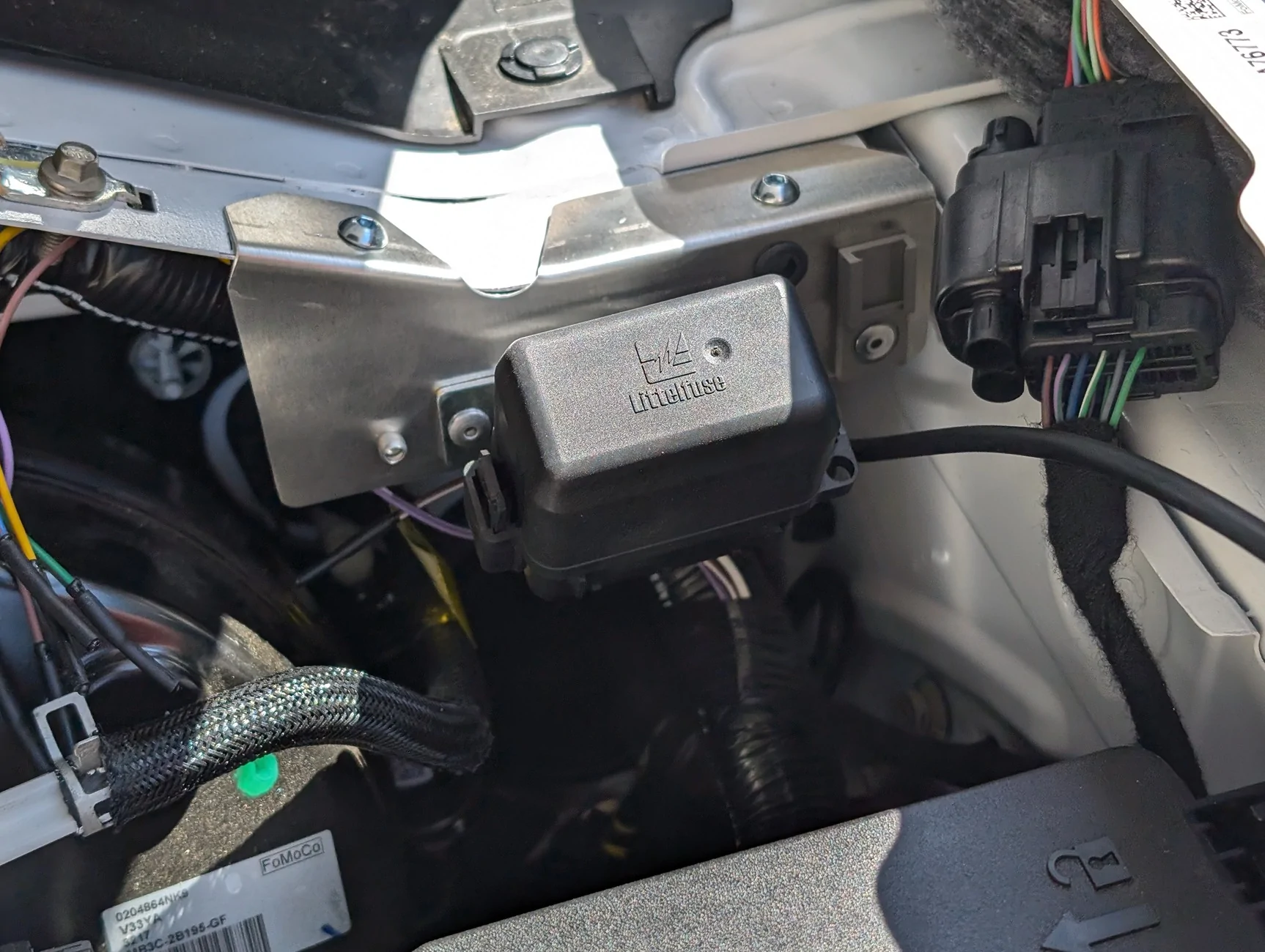
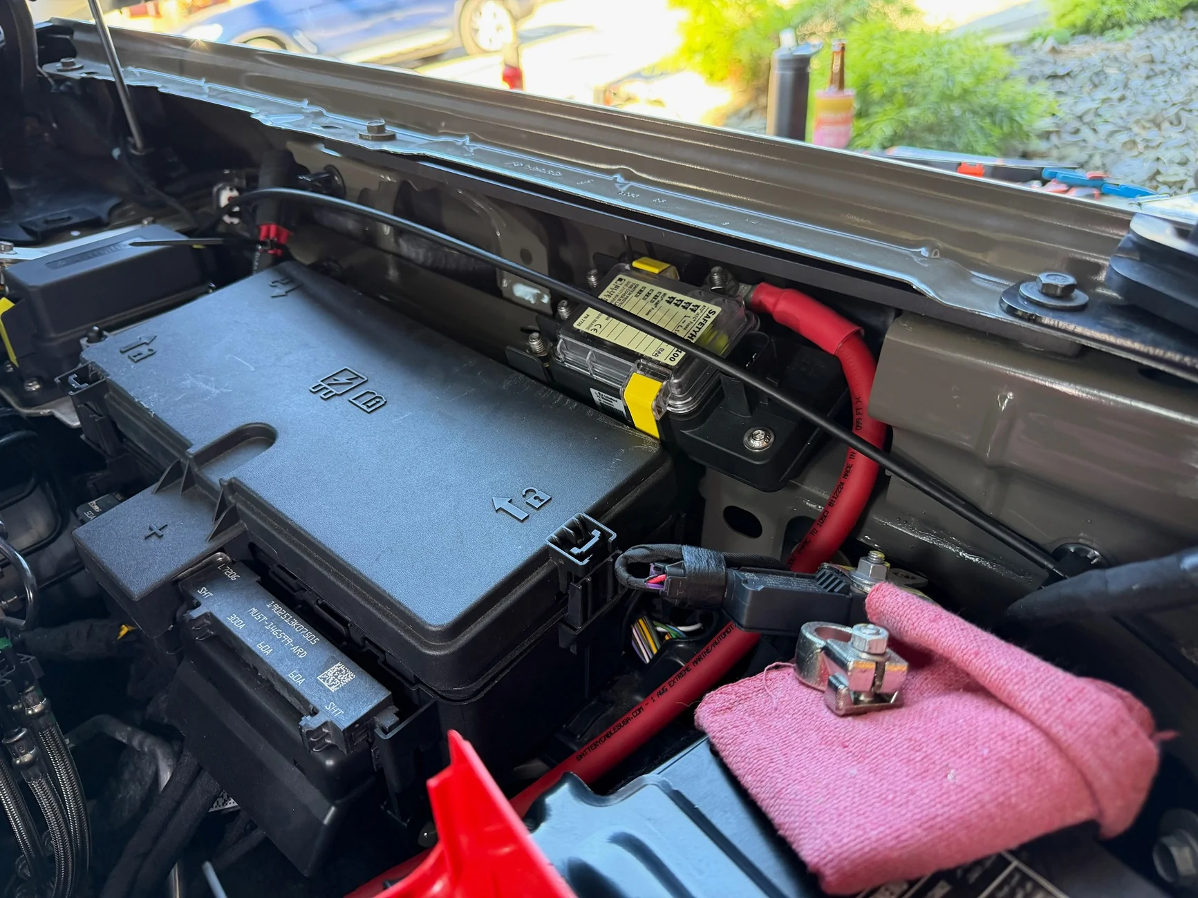
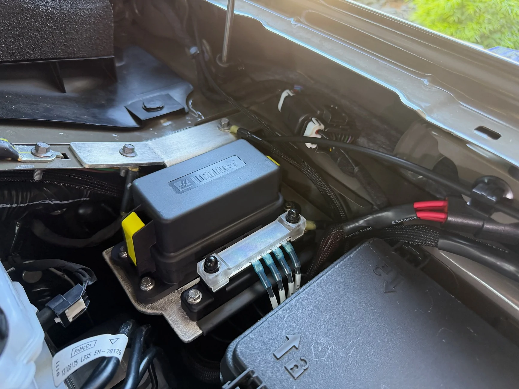
For the connection to the upfitter wiring I used a Deutsch 6 pin connector to keep things nice and clean, and keyed the AUX1-6 with positions 1-6 on the connector. And because I'm a nerd I used an adorable Epson labelmaker to create some heat shrink labels for everything. Then it was time to provide some power. Next on the list was installing the SAPS. A brief aside - I suspect many of you have been somewhat frustrated by installation instructions from aftermarket providers that are, uh, somewhat lacking. It's likely that if you're installing something over and over it is easy to forget what has been learned along the way, and those little details rarely make it into the instructions. The SAPS instructions are one of those rare sets of comprehensive instructions that actually make it really easy to install, use, and understand the "why" behind the method. The SAPS tucks nicely out of the way near the engine bay fuse box:
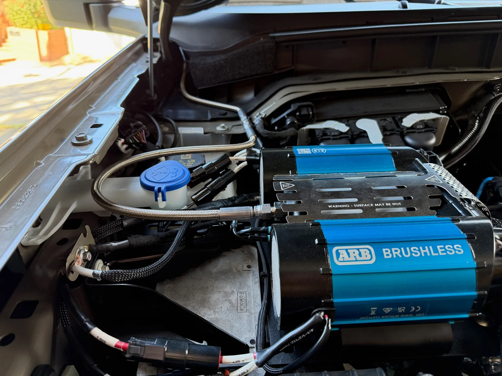
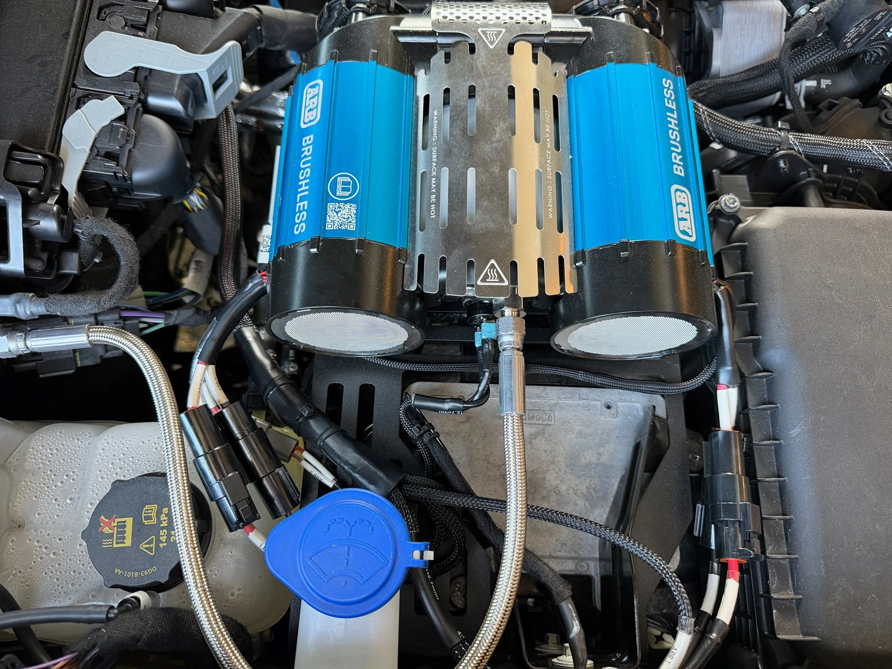
Then it was time to wire up the accessories I currently have - a light bar and the ARB brushless twin. I used the KR engine bay mounting bracket, purchased from 4x4truckleds.com. I knew that the ARB used two 60A fuses, and I wanted to use the SAPS fuse block rather than the ARB-supplied fuse block. I also wanted to run the wires along the firewall, and it was at this point the plan ran into issues. I needed to extend the +12v wires by about a foot to get to the SAPS using my preferred wiring path. I'm not a huge fan of crimped butt connectors for higher-current applications, so I figured I'd just re-pin the ARB-supplied connectors with longer wires and call it a day. When I looked up the connectors, I realized that the Metri-Pack 630 connectors are only rated for 46A. Each motor in the ARB compressor supposedly peaks at 45A, but then why use a 60A fuse? I'm sure that I'm being overly conservative, but it strikes me as fundamentally wrong to have a fuse that is rated higher than the wiring. I even emailed ARB USA to ask what the deal was, and the response was that the motors peak at 45A, run at 40A, and they're not sure why the engineers picked 60A fuses. With visions of flaming Broncos in my head I ended up completely rebuilding the ARB harness and using 60A-rated Deutsch connectors for the ARB motors.
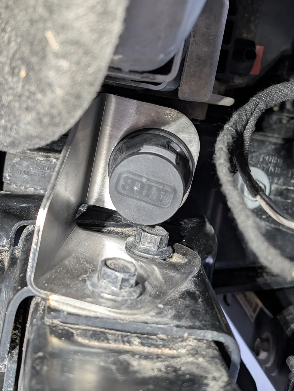
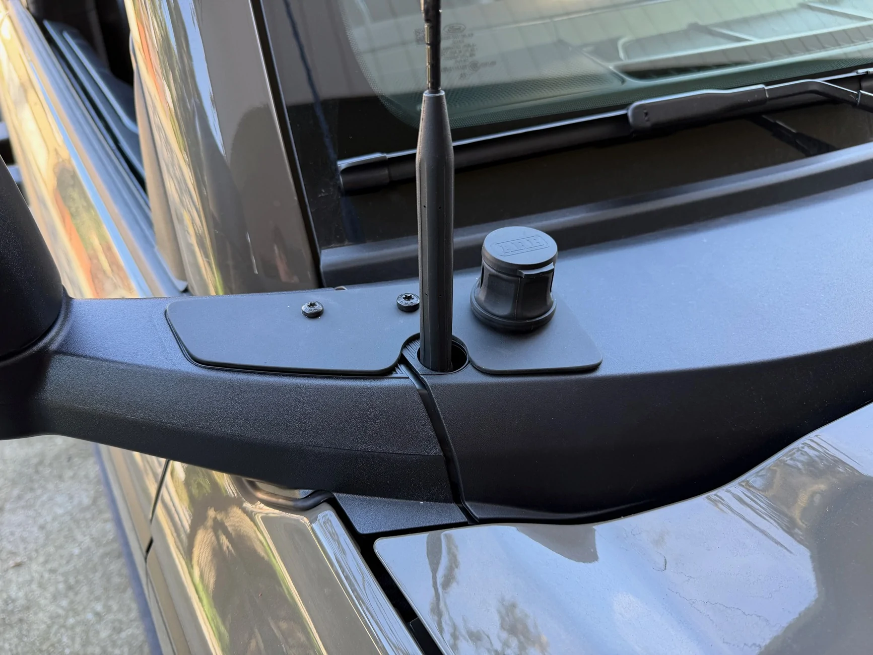
For the ARB chuck, I went with @nottinbe's solution with a slight modification. I was a bit worried about how thin the plastic cowl is for mounting the chuck, particularly given the heat that will be in the line running through the cowl. So I used some of the leftover 5052 and made and painted a simple bracket for the cowl-mounted chuck.
Also, a brief note re: the ARB compressor. When I went to hook everything up, everything was terminated electrically EXCEPT the ground for one of the motors. I was planning to ground it at the vehicle ground on the battery, but because I'd disconnected the vehicle ground I opted to wait to connect that ground leg to the vehicle ground, since I needed to loosen the bolt on the ground, and well, it's easier to loosen bolts from things that are locked in place. When I attached the vehicle ground (but before connecting the ground leg of the second motor) the compressor immediately turned on and there was a loud pop. I quickly pulled the vehicle ground off of the battery, thinking I'd screwed something up and fried something. No - something in the ARB circuit decided it was go time and turned on one of the motors. Since I hadn't connected the compressor hose yet I still had the red port plug installed. The "pop" was that plug being launched at high velocity somewhere into the engine bay or surrounds. I have no idea where it went. Don't be like me. Once I attached the ground leg to the vehicle ground and THEN attached that to the battery everything worked as designed. When I flip on AUX 6 my compressor fires right up.
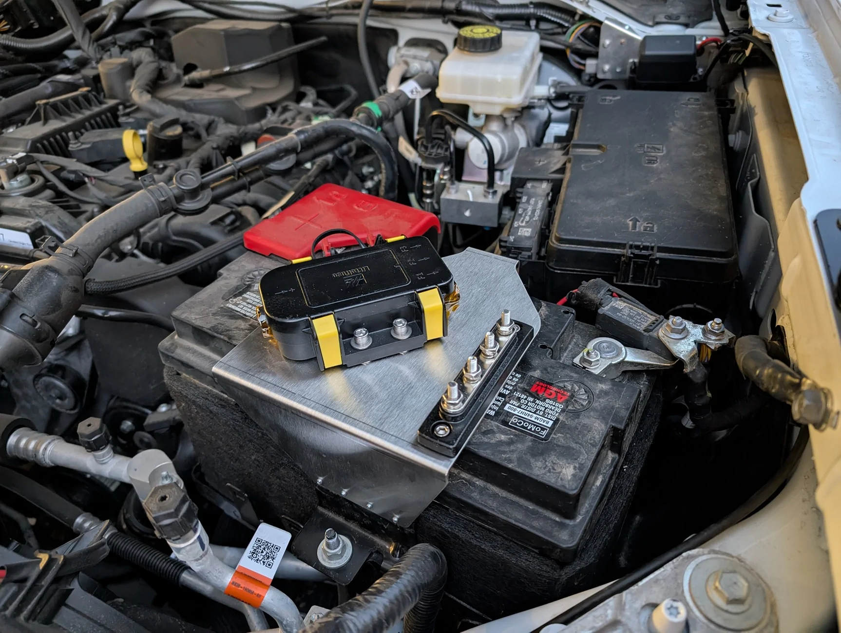
(Almost) final install photos of all components below. I want to tie down the wires a bit better, lock down the compressor hose a bit better, and add some sleeving where it contacts the washer fluid reservoir. And yes, I'm annoyed that the antenna isn't centered in the hole in the cowl. But overall very pleased with how things turned out.
I decided to use the upfitters primarily as switches to control relays in a separate, modular power distribution box, with the SAPS supplying fused power. For the PDM, I opted for a Littelfuse PDM ($22 from Waytek). Provides a lot of space for relays and / or fuses, rated up to 250A of continuous current. Due to the size of the Metri-Pack 280 terminals each circuit is good for up to 30A. Mounting it near the SAPS and the upfitters required some creativity, though, since the hood struts cut into the available space. I ended up getting a piece of 1/8" 5052 aluminum and with the use of a jigsaw, hammer, and vise getting it into a reasonable shape. 90 degree bends were made perpendicular to the grain to prevent cracking. I used metric rivnuts to hold down the PDM and a ground bus.
For the connection to the upfitter wiring I used a Deutsch 6 pin connector to keep things nice and clean, and keyed the AUX1-6 with positions 1-6 on the connector. And because I'm a nerd I used an adorable Epson labelmaker to create some heat shrink labels for everything. Then it was time to provide some power. Next on the list was installing the SAPS. A brief aside - I suspect many of you have been somewhat frustrated by installation instructions from aftermarket providers that are, uh, somewhat lacking. It's likely that if you're installing something over and over it is easy to forget what has been learned along the way, and those little details rarely make it into the instructions. The SAPS instructions are one of those rare sets of comprehensive instructions that actually make it really easy to install, use, and understand the "why" behind the method. The SAPS tucks nicely out of the way near the engine bay fuse box:
Then it was time to wire up the accessories I currently have - a light bar and the ARB brushless twin. I used the KR engine bay mounting bracket, purchased from 4x4truckleds.com. I knew that the ARB used two 60A fuses, and I wanted to use the SAPS fuse block rather than the ARB-supplied fuse block. I also wanted to run the wires along the firewall, and it was at this point the plan ran into issues. I needed to extend the +12v wires by about a foot to get to the SAPS using my preferred wiring path. I'm not a huge fan of crimped butt connectors for higher-current applications, so I figured I'd just re-pin the ARB-supplied connectors with longer wires and call it a day. When I looked up the connectors, I realized that the Metri-Pack 630 connectors are only rated for 46A. Each motor in the ARB compressor supposedly peaks at 45A, but then why use a 60A fuse? I'm sure that I'm being overly conservative, but it strikes me as fundamentally wrong to have a fuse that is rated higher than the wiring. I even emailed ARB USA to ask what the deal was, and the response was that the motors peak at 45A, run at 40A, and they're not sure why the engineers picked 60A fuses. With visions of flaming Broncos in my head I ended up completely rebuilding the ARB harness and using 60A-rated Deutsch connectors for the ARB motors.
For the ARB chuck, I went with @nottinbe's solution with a slight modification. I was a bit worried about how thin the plastic cowl is for mounting the chuck, particularly given the heat that will be in the line running through the cowl. So I used some of the leftover 5052 and made and painted a simple bracket for the cowl-mounted chuck.
Also, a brief note re: the ARB compressor. When I went to hook everything up, everything was terminated electrically EXCEPT the ground for one of the motors. I was planning to ground it at the vehicle ground on the battery, but because I'd disconnected the vehicle ground I opted to wait to connect that ground leg to the vehicle ground, since I needed to loosen the bolt on the ground, and well, it's easier to loosen bolts from things that are locked in place. When I attached the vehicle ground (but before connecting the ground leg of the second motor) the compressor immediately turned on and there was a loud pop. I quickly pulled the vehicle ground off of the battery, thinking I'd screwed something up and fried something. No - something in the ARB circuit decided it was go time and turned on one of the motors. Since I hadn't connected the compressor hose yet I still had the red port plug installed. The "pop" was that plug being launched at high velocity somewhere into the engine bay or surrounds. I have no idea where it went. Don't be like me. Once I attached the ground leg to the vehicle ground and THEN attached that to the battery everything worked as designed. When I flip on AUX 6 my compressor fires right up.
(Almost) final install photos of all components below. I want to tie down the wires a bit better, lock down the compressor hose a bit better, and add some sleeving where it contacts the washer fluid reservoir. And yes, I'm annoyed that the antenna isn't centered in the hole in the cowl. But overall very pleased with how things turned out.
Sponsored