
Sponsored

TPMS Module not picking up sensor

Snacktime

Black Diamond
Well-Known Member
First Name
Nate
Joined
Jul 14, 2020
Threads
73
Messages
3,980
Reaction score
9,958
Location
Sac-a-tomatoes
Vehicle(s)
Bronco, F150
Your Bronco Model
Black Diamond
Clubs
 
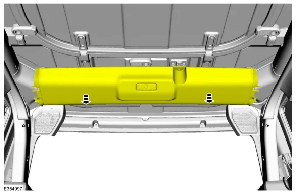
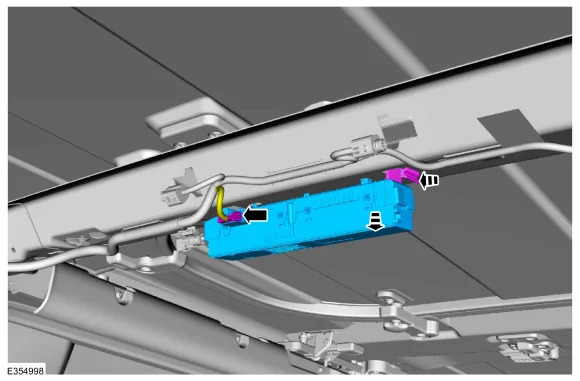
Anyone know where the TPMS detection module is? Google says behind passenger rear panel?

@Ducati1098 got a magic diagram?

Trouble shooting a tire pressure sensor not reading and it's definitely not the in tire sensor. I think it might be my giant metal rear tub. Might need to relocate the detector forward 1-2ft.
Sponsored
 

Ducati1098

Wildtrak
Well-Known Member
Joined
Jul 14, 2020
Threads
26
Messages
9,975
Reaction score
23,176
Location
Midwest
Vehicle(s)
2022 Bronco Wildtrak, 2006 Corvette Z06, 2012 Ford Fusion
Your Bronco Model
Wildtrak
Clubs
 
Anyone know where the TPMS detection module is? Google says behind passenger rear panel?

@Ducati1098 got a magic diagram?

Trouble shooting a tire pressure sensor not reading and it's definitely not the in tire sensor. I think it might be my giant metal rear tub. Might need to relocate the detector forward 1-2ft.
TPMS uses the RTM (radio transceiver module)
It’s at the very rear/top of the roll bar under the trim:

Ford Bronco TPMS Module not picking up sensor 1787451188234-gf

Ford Bronco TPMS Module not picking up sensor 1787451374037-vq
 
OP
OP
Snacktime

Snacktime

Black Diamond
Well-Known Member
First Name
Nate
Joined
Jul 14, 2020
Threads
73
Messages
3,980
Reaction score
9,958
Location
Sac-a-tomatoes
Vehicle(s)
Bronco, F150
Your Bronco Model
Black Diamond
Clubs
 
@Ducati1098 now that really throws a wrench in my thinking that I was obstructing the signal some how? Must be the module as I can't get a reading off drivers rear no matter how I rotate the tires.
 

Ducati1098

Wildtrak
Well-Known Member
Joined
Jul 14, 2020
Threads
26
Messages
9,975
Reaction score
23,176
Location
Midwest
Vehicle(s)
2022 Bronco Wildtrak, 2006 Corvette Z06, 2012 Ford Fusion
Your Bronco Model
Wildtrak
Clubs
 
@Ducati1098 now that really throws a wrench in my thinking that I was obstructing the signal some how? Must be the module as I can't get a reading off drivers rear no matter how I rotate the tires.
Could be RFI maybe? Hard to say. The RTM receives the signal from the sensors, then communications all the information to the BCM.

But it communicates to the BCM over a LIN network, so if only one sensor isn’t working, it can’t be the LIN. I suppose it could be an issue with the BCM still though.
 
OP
OP
Snacktime

Snacktime

Black Diamond
Well-Known Member
First Name
Nate
Joined
Jul 14, 2020
Threads
73
Messages
3,980
Reaction score
9,958
Location
Sac-a-tomatoes
Vehicle(s)
Bronco, F150
Your Bronco Model
Black Diamond
Clubs
 
@Ducati1098 rotate the tires, pull the battery and the drivers rear doesn't read after reset. Lost it while driving on the freeway in 110F heat two weeks ago. Going to pull the plastic tomorrow and get the part number as I see there are 2 different options. No codes, so it has be a internal sensor of some type that determines which tire it detects. For $40 off eBay it's worth a shot in the dark.
 

Ducati1098

Wildtrak
Well-Known Member
Joined
Jul 14, 2020
Threads
26
Messages
9,975
Reaction score
23,176
Location
Midwest
Vehicle(s)
2022 Bronco Wildtrak, 2006 Corvette Z06, 2012 Ford Fusion
Your Bronco Model
Wildtrak
Clubs
 
Here’s everything from the description and operation section of the workshop manual:


TPMS Function

NOTE:
When directed to train any TPMS sensors, use only the sensor training procedure outlined in this manual. Do not use the TPMS reset procedure outlined in the Owner's Literature as this procedure does notprogram new sensors to the module.

The TPMS uses 4 valve stem mounted sensors to monitor tire pressure. These sensors wirelessly transmit tire pressure data to the RTM . The RTM is a radio signal receiver which collects the tire pressure data and sends the information to the BCM along a LIN . All TPMSfunctions are controlled by the BCM . The BCMcompares the tire pressure data sent by the RTM with a programmed tire pressure. This programmed pressure is specified on the VC label and cannot be changed. If the actual tire pressure is less than the programmed tire pressure, the BCM sends a low tire pressure message to the IPC along the HS-CAN3 . The IPC responds by illuminating the TPMS warning indicator and displaying a low tire pressure message in the message center. The TPMS sensors are trained (calibrated) to the BCM which records the unique identifier for each TPMS sensor and records the location of each sensor based on the training (calibration) order. The BCM sends messages to the IPCby first sending the information along the HS-CAN1 to the GWM which then sends the information to the IPC along the HS-CAN3 .

The diagnostic scan tool is useful in diagnosing TPMSconcerns and may be used to verify the accuracy of the tire pressure data transmitted by the TPMS sensors. This is accomplished by comparing the BCM tire pressure PIDdata to the actual tire pressure using a digital tire pressure gauge.

It is necessary to train (calibrate) the TPMS sensors after a tire rotation on vehicles with different front and rear tire pressures. The BCM does not automatically recognize the sensor identifiers have been moved to different positions and retains the original position information for each sensor.
Refer to: Tire Pressure Monitoring System (TPMS) Sensor Location Calibration (204-04B Tire Pressure Monitoring System (TPMS), General Procedures).

Wheel Rotation and Sensor Training Techniques

Training known good sensors from another vehicle can help determine whether the concern is with a sensor or the RTM . This technique cannot help determine whether the concern is due to RFI as some RFI source could be preventing the RTM from receiving the tire pressure status from the known good sensors as well as the original sensors.

If the RTM in the suspect vehicle cannot train any of the original sensors and, likewise, cannot train known good sensors from another vehicle, then the concern is with the module or RFI and not with the original sensors. The original sensors should not be replaced. If a sensor in a certain location has caused several events, yet the sensor trains and seems to operate normally, moving that particular wheel to a different location on the vehicle is a good way to isolate the concern to a certain sensor/wheel location. Rotate the wheels and road test the vehicle. This can be done in an attempt to replicate the concern and help determine if the concern followed the sensor or remained in the original sensor location.

If the vehicle has been stationary for more than 30 minutes, the sensors go into a "sleep mode" to conserve battery power and need to be "woken up" so they transmit the latest tire pressure information to the RTM .
Refer to: Tire Pressure Monitoring System (TPMS) Sensor Activation (204-04B Tire Pressure Monitoring System (TPMS), General Procedures).

Training Sensors in a Different Order

If the first sensor fails the TPMS training procedure, the BCM aborts the entire procedure. Starting the training procedure at a different wheel is a technique which can be used to determine if the remaining sensors can train to the module. This can help save time determining if one sensor is damaged, other sensors are having concerns or the BCM is experiencing training difficulties with a certain TPMS sensor location.

TPMS Warning Indicator

The TPMS warning indicator is used to indicate both a low tire pressure event and a possible system fault condition. The message center displays additional information associated with the low tire pressure event or the system fault condition. Occasionally, the warning indicator and message center indicate faults that cannot be resolved by the customer. Treat these as TPMS faults that must be serviced.

TPMS Warning Indicator Illuminates Continuously

The TPMS warning indicator remains on continuously and the message center displays LOW TIRE PRESSURE when any of the tire pressures fall below the low pressure limit. When this condition exists, adjust the tire pressure to the recommended cold tire pressure indicated on the VC label.

TPMS Warning Indicator Flashes

The TPMS warning indicator flashes for 70 seconds and then remains on continuously when the ignition is set to ON and the TPMS is malfunctioning. The TPMS status ( TPMS _STATUS) PID can be used to determine why the TPMS warning indicator is flashing.

  • Tire Pressure Sensor Fault — The message center displays TIRE PRESSURE SENSOR FAULT when a TPMS sensor is malfunctioning.
  • No communication with the BCM — The TPMSwarning indicator illuminates when the IPC has not received any signals from the BCM for more than 5 seconds. The message center displays TIRE PRESSURE MONITOR FAULT.
  • Tire Pressure Monitor Fault — The message center displays TIRE PRESSURE MONITOR FAULT when the TPMS is malfunctioning.
TPMS PID Definitions

The BCM monitors the TPMS status. Use the diagnostic scan tool to view the current status of the TPMS using the ( TPMS _STATUS) PID . This helps identify the current system status and may aid in diagnosing the system. The PID has 4 valid states:

  • TPMS _STATUS PID displays SENSOR FAULT if the BCM has not received the tire pressure data from 1 to 3 TPMS sensors for 20 minutes when vehicle speed is above 32.2 km/h (20 mph).
  • TPMS _STATUS PID displays SYSTEM FAULT if the BCM has not received the tire pressure data from all 4 TPMS sensors for 20 minutes when vehicle speed is above 32.2 km/h (20 mph).
  • TPMS _STATUS PID displays LOW if the BCM has detected that at least 1 TPMS sensor is reporting low tire pressure.
  • TPMS _STATUS PID displays SYSTEM ACTIVE if the TPMS is functioning normally.
Last Warning Event PID Definitions

The TPMS uses the TPMS last warning event PID to store detailed information about the last 5 times the TPMS warning indicator was activated. These PID can be used to acquire more information about a particular TPMS event, but must be used carefully.


PIDDefinitionEVT1_AGE_IGN through EVT5_AGE_IGN The number of key cycles since the TPMS was activated. This PID cycles from zero to 255 and then starts over from zero again. This can be used to determine how long ago a TPMSevent occurred and the time (in key cycles) between events. EVT1_TR_LOC through EVT5_TR_LOC This is the last programmed location for the TPMS sensor identifier causing each TPMS event. Due to tire rotation, the sensor may no longer be at the original location. It is suggested that all the PID be recorded, the system retrained, and then the sensor identifier PID be used to pinpoint the actual location of each sensor. EVT1_PRES_BP through EVT5_PRES_BP This is the tire pressure associated with each TPMS indicator event. This can be used along with the function code to clearly identify the TPMSevents that were strictly due to low pressure. It can also be used to determine when a sensor is transmitting inaccurate tire pressure. EVT1_SNSR_ST through EVT5_SNSR_ST
  • Describes the warning status of each TPMS event by using the information received from the TPMS _STATUS PID . If there is a communication concern, the status could be NORMAL.
  • UNKNOWN
  • NORMAL (normal operation)
  • LOW (low pressure event)
  • FAULT (sensor fault or system fault)
EVT1_SNSR_ID through EVT5_SNSR_ID This is the identifier of the sensor involved in each TPMS event. EVT1 is the most recent event that triggered the TPMS warning indicator.


RFI

RFI can be caused by:

  • Video equipment has been found to cause RFIespecially when the video and power supply lines are near the TPMS .
  • Anti-theft alarms (even those installed by the dealership) have been found to create enough RFIto cause the TPMS to malfunction or lose considerable range. These anti-theft alarms can be difficult to locate, as they are usually hidden somewhere out of the way for reduced accessibility.
  • Many in-vehicle cell phone chargers have been found to cause considerable RFI . The vehicles with the power point closest to the RTM are the most affected. It must be noted that most cell phone chargers do not produce high levels of RFI all the time. This depends on the state of charge of the cell phone battery. The phone battery must be almost completely discharged in some cases.
  • Power supplies and DC / AC inverters typically create a lot of RFI . Most consumer grade equipment has very little filtering or shielding.
Using Hit Rate PID to Determine the Presence of RFI

If an intermittent RFI issue is suspected, the information contained in the last 5 TPMS warning event PID can be combined with specific PID from the BCM to determine which TPMS sensors are being affected and if a RFIsource is currently present in the vehicle.

The BCM module contains PID that keep track of the number of TPMS messages received from the 4 trained TPMS sensors. These PID can provide insight on the performance of the TPMS , and can help establish the presence of an RFI source.

  • TPM_HITS_LF (Tire Pressure Monitor Hit Rate Left Front) – The number of TPMS messages received by the BCM module from the LH front sensor
  • TPM_HITS_RF (Tire Pressure Monitor Hit Rate Right Front) – The number of TPMS messages received by the BCM module from the RH front sensor.
  • TPM_HITS_LRO (Tire Pressure Monitor Hit Rate Left Rear Outer) – The number of TPMS messages received by the BCM module from the LH rear sensor
  • TPM_HITS_RRO (Tire Pressure Monitor Hit Rate Right Rear Outer) – The number of TPMSmessages received by the BCM module from the RH rear sensor.
Method for determining if a RFI issue has been affecting the TPMS :

  1. Collect the last 5 TPMS events and determine if they were due to system faults or low tire air pressure.
  2. Collect the TPMS Hit Rate PID counters and compare them to the last 5 TPMS events.
  3. If the TPMS Hit Rate PID counters are significantly different from each other or if the locations with lower hit rate values show up as fault locations in last 5 TPMS events and BCM DTC B124D:02 (Tire Pressure Sensor: General Signal Failure) is present, an intermittent RFI source is most likely preventing the signals from these TPMS sensors from reaching the RTM .
  4. An intermittent RFI source can also be the case when all 4 TPMS sensors show up in the last 5 fault events and BCM DTC B1182:00 ( TPMS : No Sub Type Information) is present. The possible cause would a strong source of RFI noise.
Original Equipment Manufacturer (OEM) Modules

In some cases the RFI may actually be caused by a module or ground on the vehicle. Depending on the severity of the concern, a dirty ground, improperly built ground shield or module can disable the system. Modules which have microcontrollers using clock circuits to create timing pulses for the microprocessor may radiate RFI .

Using Customer Electronics to Pinpoint RFI

This method can be a way to determine the cause of a concern before the sensors and module are replaced with little or no effect on system performance. Discuss with the customer what types of devices were being used when the event occurred. Determine which power points were being used and, if necessary, ask the devices be activated to determine their affect on the TPMS .

Options for Eliminating Intermittent TPMS Operation Caused by RFI

  • If an Original Equipment Manufacturer (OEM) component or customer device is causing a RFIconcern, replace the device.
  • If a phone charger is causing a RFI concern, the customer should consult with their cell phone provider to acquire a different battery charger.
  • If a device such as a dealer installed anti-theft alarm is causing a RFI concern, move the device to another location in the vehicle. In the case of a portable device move the power cord to another power point location.
In summary, if the RFI source is present and cannot be moved or replaced, the intermittent concern remains. The TPMS must accept the unwanted system operation the RFI can cause.

Component Description

BCM

The BCM is a multifunction module which monitors all sensor inputs and all CAN messages relating to the TPMS . The BCM records and retains the unique sensor identifier of each TPMS sensor.

The BCM retains the previous sensor location information following a tire rotation. For the BCM to learn the new sensor location, the sensors must be trained (calibrated) to the BCM .
Refer to: Tire Pressure Monitoring System (TPMS) Sensor Location Calibration (204-04B Tire Pressure Monitoring System (TPMS), General Procedures).
Additionally, the sensors must be trained when a new BCM is installed.

When installing a new BCM , there are several procedures that must be carried out in order for the module to function correctly. These procedures include, but are not limited to; PMI , anti-theft parameter reset, programming keyless entry remote and setting customer preferences.
Refer to: Body Control Module (BCM) (419-10 Multifunction Electronic Modules, Removal and Installation).

Additionally, the sensors must be trained when a new BCM installed.TPMS pressure data is cleared from the BCM when the module is flashed or reconfigured. When the data is cleared, the tire pressure DID's reset to the factory default of 1033 kPa (149.96 psi) and the IPCdisplays dashes for the tire pressures. The sensors must be activated to transmit the latest tire pressure information.

RTM

The RTM is a radio signal receiver which collects the tire pressure data from the TPMS sensors.


TPMS Sensor

Each of the 4 TPMS sensors contain a battery, a tire pressure sensor and a radio transmitter. The TPMS sensor radio transmissions are sent approximately once every 60 seconds when the vehicle speed exceeds 32.2 km/h (20 mph).
Sponsored


Top