- First Name
- Tom
- Joined
- Sep 14, 2023
- Threads
- 5
- Messages
- 147
- Reaction score
- 281
- Location
- New Hampshire
- Vehicle(s)
- 2023 Bronco Wildtrak
- Your Bronco Model
- Wildtrak
- Thread starter
- #1
Having installed AMP PowerStep Smart Series running boards on my Bronco here are some tips to make your install go smoother and hopefully quicker. I made the mistakes so you don't have to ") .
.
The large hex flange bolts for mounting the motor linkage and idler linkages are pre-coated with a thread locker. The consistency reminds me of plumbers dope that has dried to a flexible semi-hard paste. I found that tightening the bolts took extreme effort that made the install difficult with hand ratchets. I started with a 3/8” racket and then moved up to a 1/2” drive ratchet. Still difficult. Particularly the bottom front bolt which requires a racketing wrench to reach inside the idler assembly to tighten the bolt. I finally removed the brackets and used my power impact gun to run the bolts all the way in and then out of the holes of the under body. This removed the thread locker making the bolt tightening much easier. Note I did use my own LocTite blue thread lock sealer on the bolts for assembly. Do not skip this part. You do not want the bolts to loosen later.
Step #2 says to snug up the bolts but do not torque. I did this the first time around. Having to realign the drivers side later, I found leaving the bolts loose enough to rattle the bracket back and forth with your hand instead of snugging the bolts worked better when moving on to the torque phase.
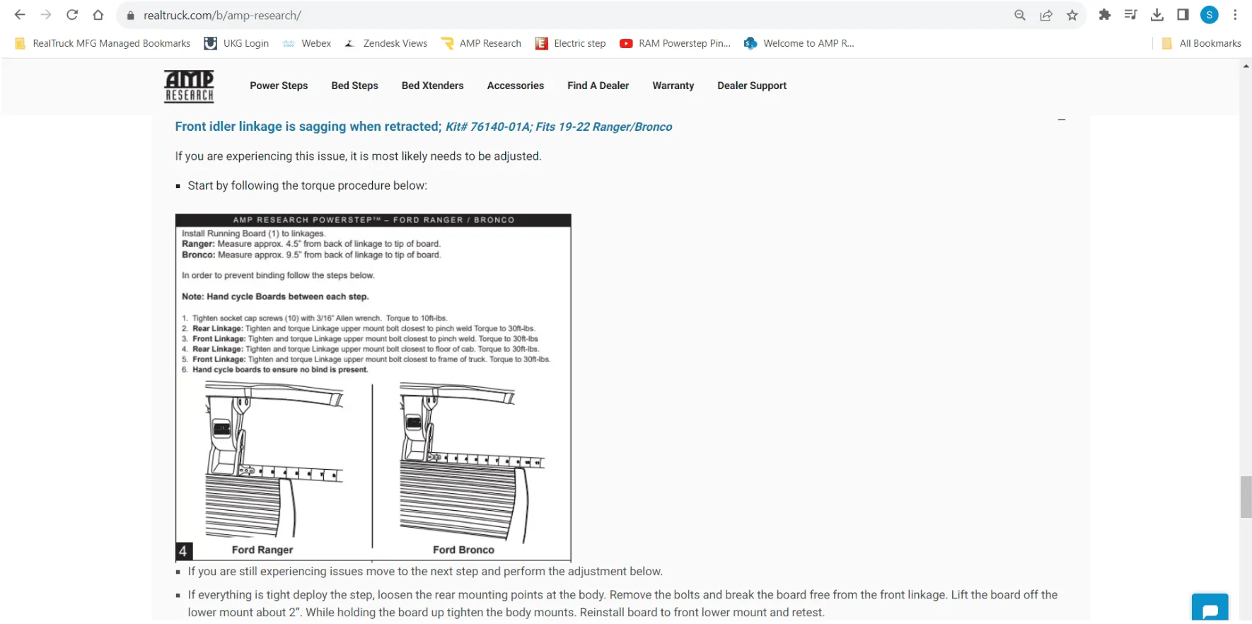
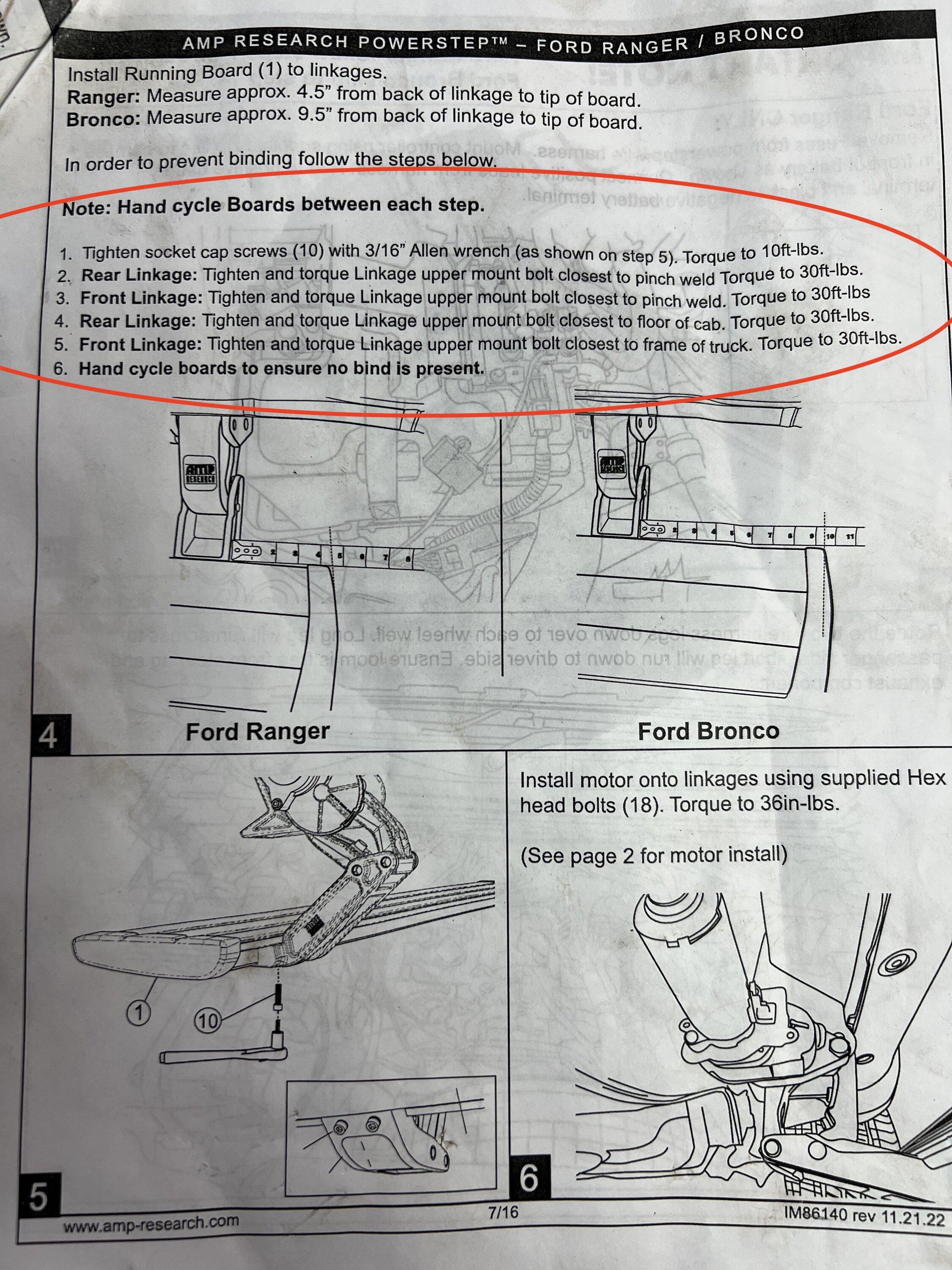
FOLLOW STEP #4 TORQUE SEQUENCE EXACTLY! It does make a difference! The proper sequence will save time later when you don’t have to redo a step because of binding.
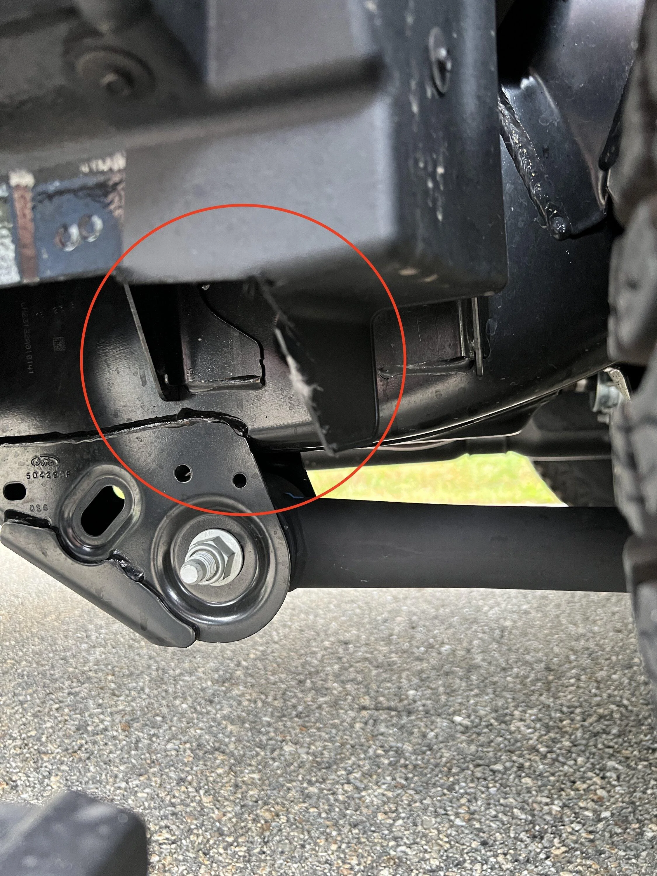
They don't mention it in the instructions but on my 2023 Wildtrak the rear of the step hits the rear wheel front splash guard. I had to trim both sides for the step to clear when retracted. You could also probably just trim the back of the step an inch or so to clear the splash guard?
When installing the running board lights you do not have to drill a hole in the pinch weld seam. Use the existing holes. I used the rear most hole for the back door. I used the 2nd hole from the front for the front door. Grab some rubber grommets from the hardware store and use these in the holes before running the wires through.
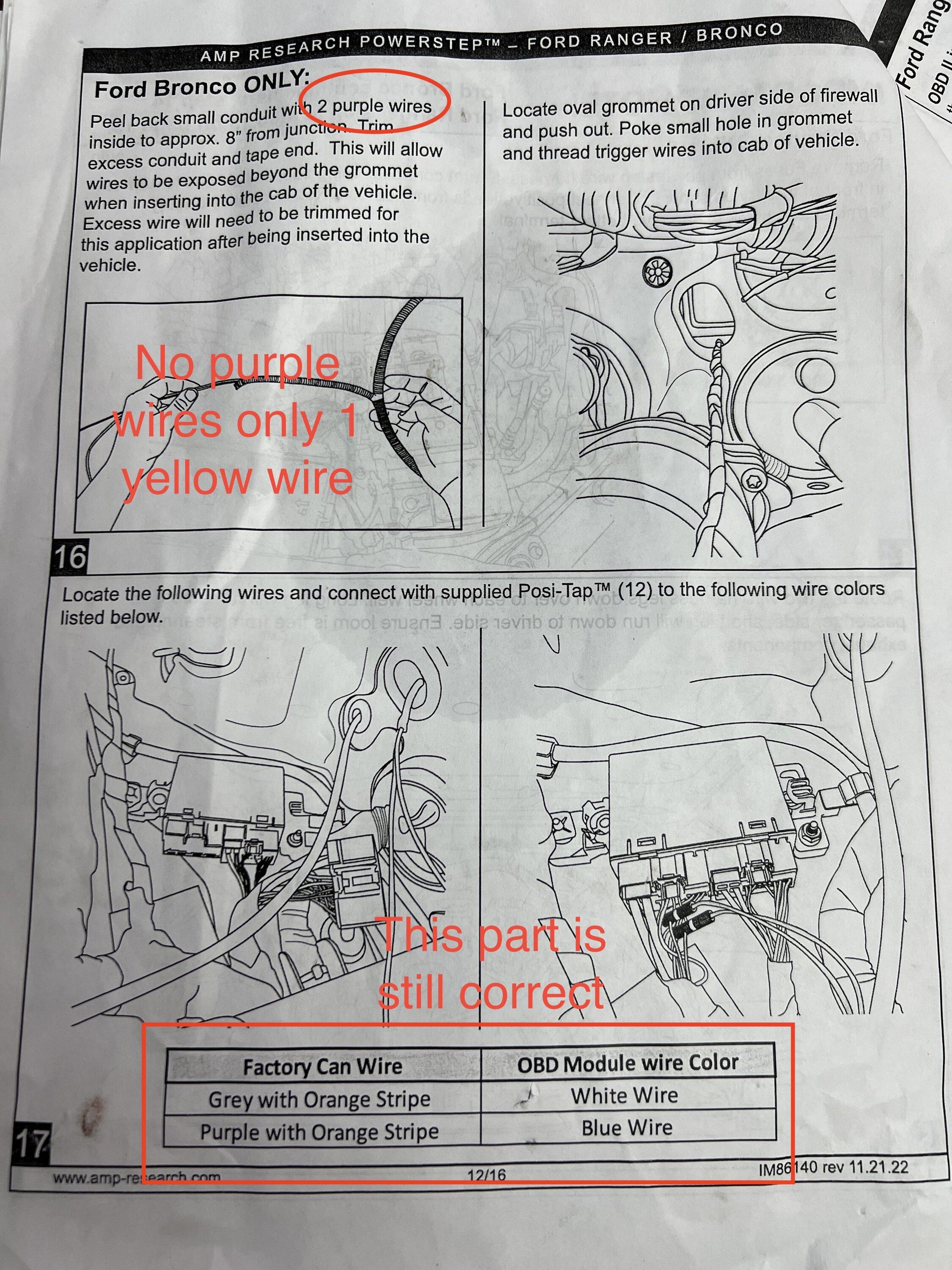
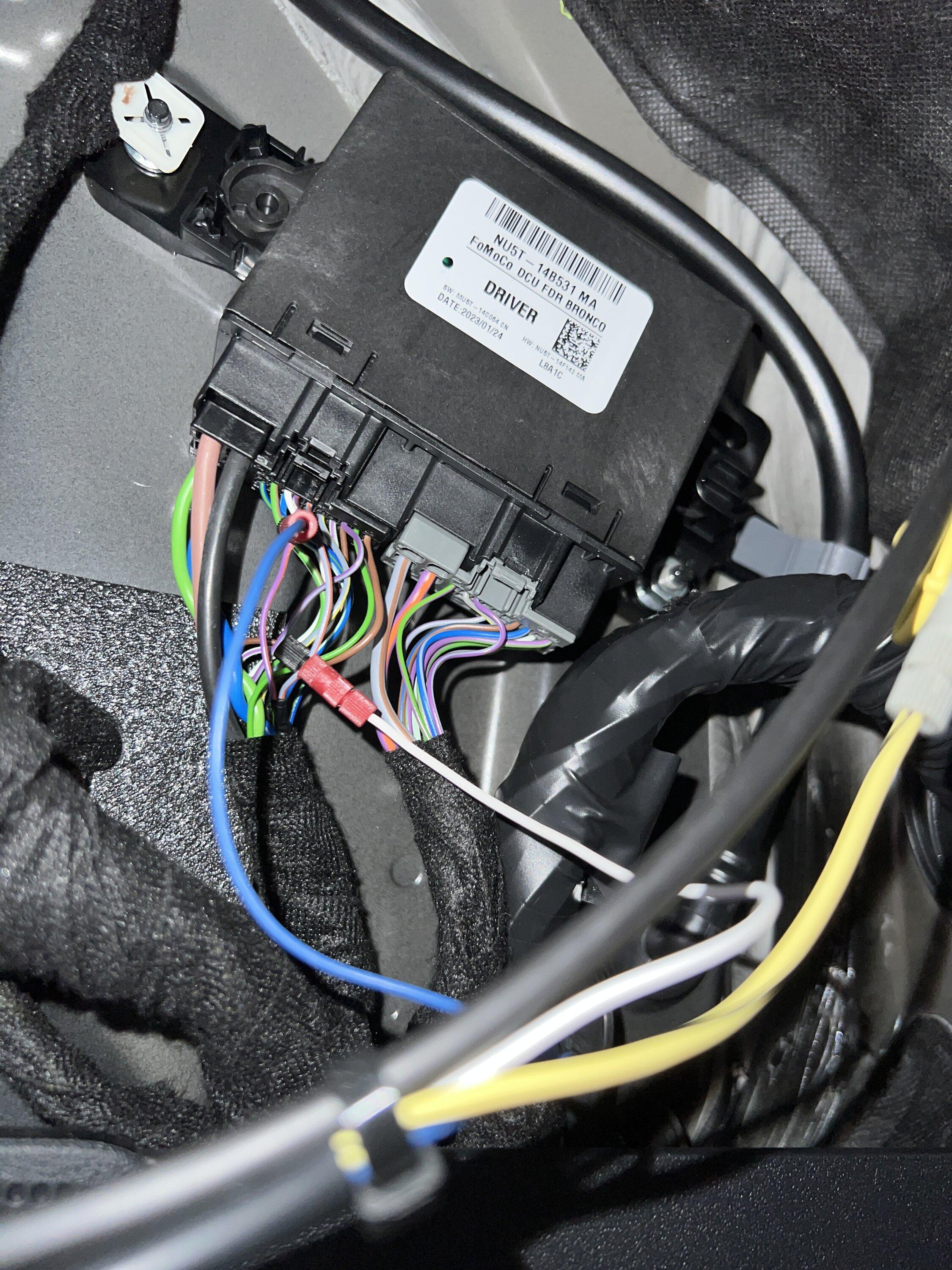
For wiring, Step #16 says to use the 2 purple wires. THERE ARE NO PURPLE WIRES! AMP changed the wiring harness to 1 YELLOW wire. The yellow wire was sticking out of the drivers side harness almost at the end directly below where the divers seat is located. Open the split loom conduit in the engine bay area and just pull the yellow wire out of the loom. You only need a foot or two to reach inside the drivers footwell. You can cut the rest off. Run the yellow wire through the firewall grommet as they directed for the purple wire.
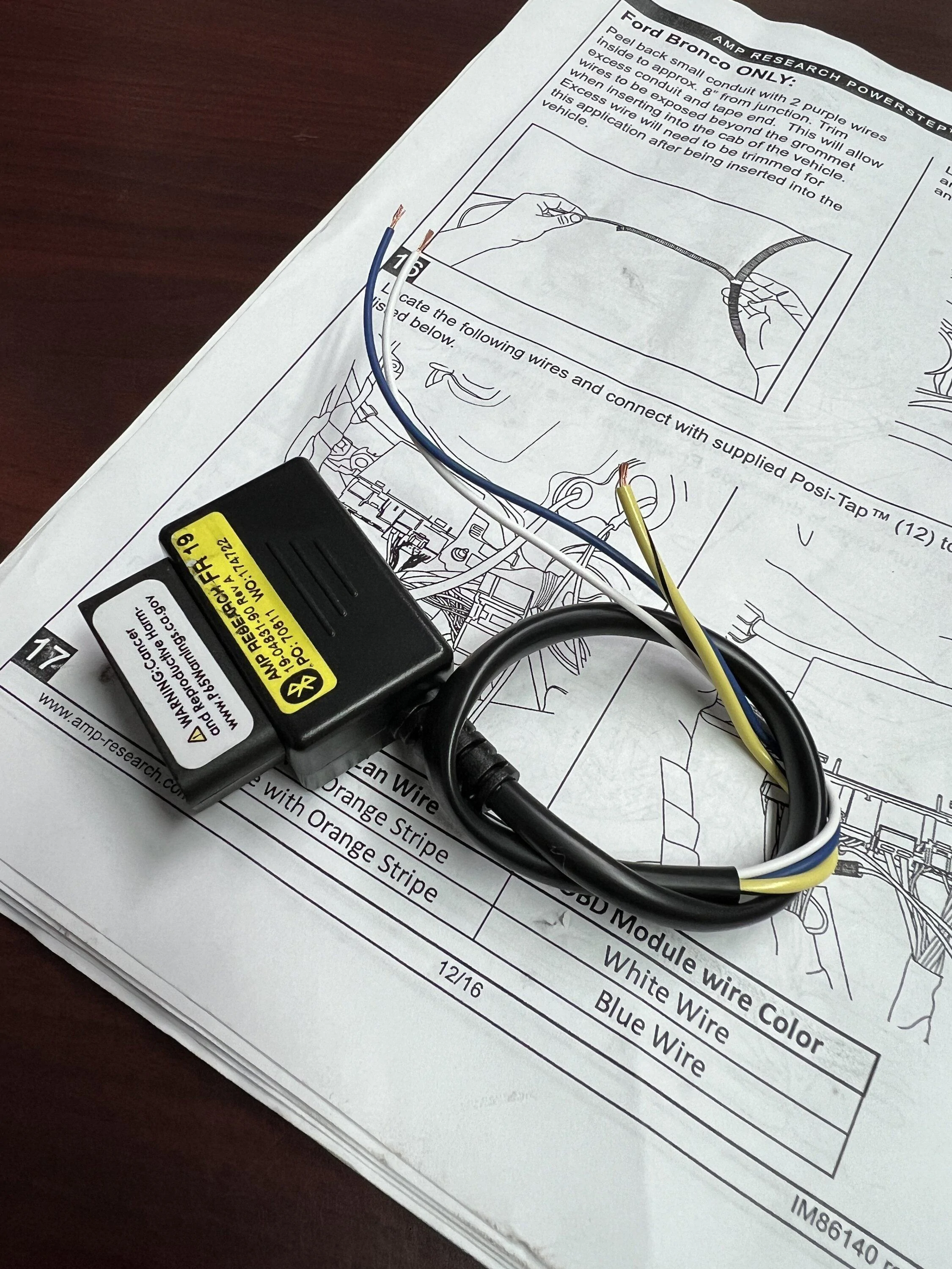
The OBD plug provided from AMP has 3 wires, a yellow, blue and white wire. The yellow wire from the wire harness connects to the yellow OBD wire. The blue and white OBD plug wires get connected to the Factory Can Wiring exactly as the instructions state. The Posi-tap wire connectors provided for the CAN wires work but be careful not to drop the freaken little caps. I put a rag under the CAN wires to prevent losing one behind the kick panel if you drop it. You will drop one…
Installing the electric motors to the linkage assembly is not hard but the mounting bolts toward the frame on the inside is extremely difficult to reach. I have a pretty good tool collection and tried a bunch of different tools but a quality ratchet wrench moves just enough to eventually tighten the inside bolt. The cheap little plastic push clips that hold the motor cover in place are easy to break or lose. I went to the hardware store and picked up some plastic retainer clips.
On a final note my drivers side step did not retract evenly along the rocker panel. The front was hanging lower than the rear of the step. I took the step off and redid it following the torque sequence exactly. The step did work more smoothly but still sagged more at them front than the rear. I ended up putting a washer under the front lower idler linkage mounting bolt. The washer was added at the correct point during the torquing sequence and checked to make sure there was no binding in the movement. This worked perfect and the step now lines up evenly.
Total time for my install (making mistakes and redoing some of the above steps) was 6 hours for mounting and wiring. Then another 2 hours realigning the drivers side step a second time because the step was lower at the front than the rear when retracted.

.
** Edited to add pics of trimming the rear wheel front splash guard.
.The large hex flange bolts for mounting the motor linkage and idler linkages are pre-coated with a thread locker. The consistency reminds me of plumbers dope that has dried to a flexible semi-hard paste. I found that tightening the bolts took extreme effort that made the install difficult with hand ratchets. I started with a 3/8” racket and then moved up to a 1/2” drive ratchet. Still difficult. Particularly the bottom front bolt which requires a racketing wrench to reach inside the idler assembly to tighten the bolt. I finally removed the brackets and used my power impact gun to run the bolts all the way in and then out of the holes of the under body. This removed the thread locker making the bolt tightening much easier. Note I did use my own LocTite blue thread lock sealer on the bolts for assembly. Do not skip this part. You do not want the bolts to loosen later.
Step #2 says to snug up the bolts but do not torque. I did this the first time around. Having to realign the drivers side later, I found leaving the bolts loose enough to rattle the bracket back and forth with your hand instead of snugging the bolts worked better when moving on to the torque phase.
FOLLOW STEP #4 TORQUE SEQUENCE EXACTLY! It does make a difference! The proper sequence will save time later when you don’t have to redo a step because of binding.
They don't mention it in the instructions but on my 2023 Wildtrak the rear of the step hits the rear wheel front splash guard. I had to trim both sides for the step to clear when retracted. You could also probably just trim the back of the step an inch or so to clear the splash guard?
When installing the running board lights you do not have to drill a hole in the pinch weld seam. Use the existing holes. I used the rear most hole for the back door. I used the 2nd hole from the front for the front door. Grab some rubber grommets from the hardware store and use these in the holes before running the wires through.
For wiring, Step #16 says to use the 2 purple wires. THERE ARE NO PURPLE WIRES! AMP changed the wiring harness to 1 YELLOW wire. The yellow wire was sticking out of the drivers side harness almost at the end directly below where the divers seat is located. Open the split loom conduit in the engine bay area and just pull the yellow wire out of the loom. You only need a foot or two to reach inside the drivers footwell. You can cut the rest off. Run the yellow wire through the firewall grommet as they directed for the purple wire.
The OBD plug provided from AMP has 3 wires, a yellow, blue and white wire. The yellow wire from the wire harness connects to the yellow OBD wire. The blue and white OBD plug wires get connected to the Factory Can Wiring exactly as the instructions state. The Posi-tap wire connectors provided for the CAN wires work but be careful not to drop the freaken little caps. I put a rag under the CAN wires to prevent losing one behind the kick panel if you drop it. You will drop one…
Installing the electric motors to the linkage assembly is not hard but the mounting bolts toward the frame on the inside is extremely difficult to reach. I have a pretty good tool collection and tried a bunch of different tools but a quality ratchet wrench moves just enough to eventually tighten the inside bolt. The cheap little plastic push clips that hold the motor cover in place are easy to break or lose. I went to the hardware store and picked up some plastic retainer clips.
On a final note my drivers side step did not retract evenly along the rocker panel. The front was hanging lower than the rear of the step. I took the step off and redid it following the torque sequence exactly. The step did work more smoothly but still sagged more at them front than the rear. I ended up putting a washer under the front lower idler linkage mounting bolt. The washer was added at the correct point during the torquing sequence and checked to make sure there was no binding in the movement. This worked perfect and the step now lines up evenly.
Total time for my install (making mistakes and redoing some of the above steps) was 6 hours for mounting and wiring. Then another 2 hours realigning the drivers side step a second time because the step was lower at the front than the rear when retracted.

.

** Edited to add pics of trimming the rear wheel front splash guard.
Sponsored
Last edited: