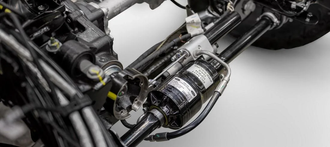
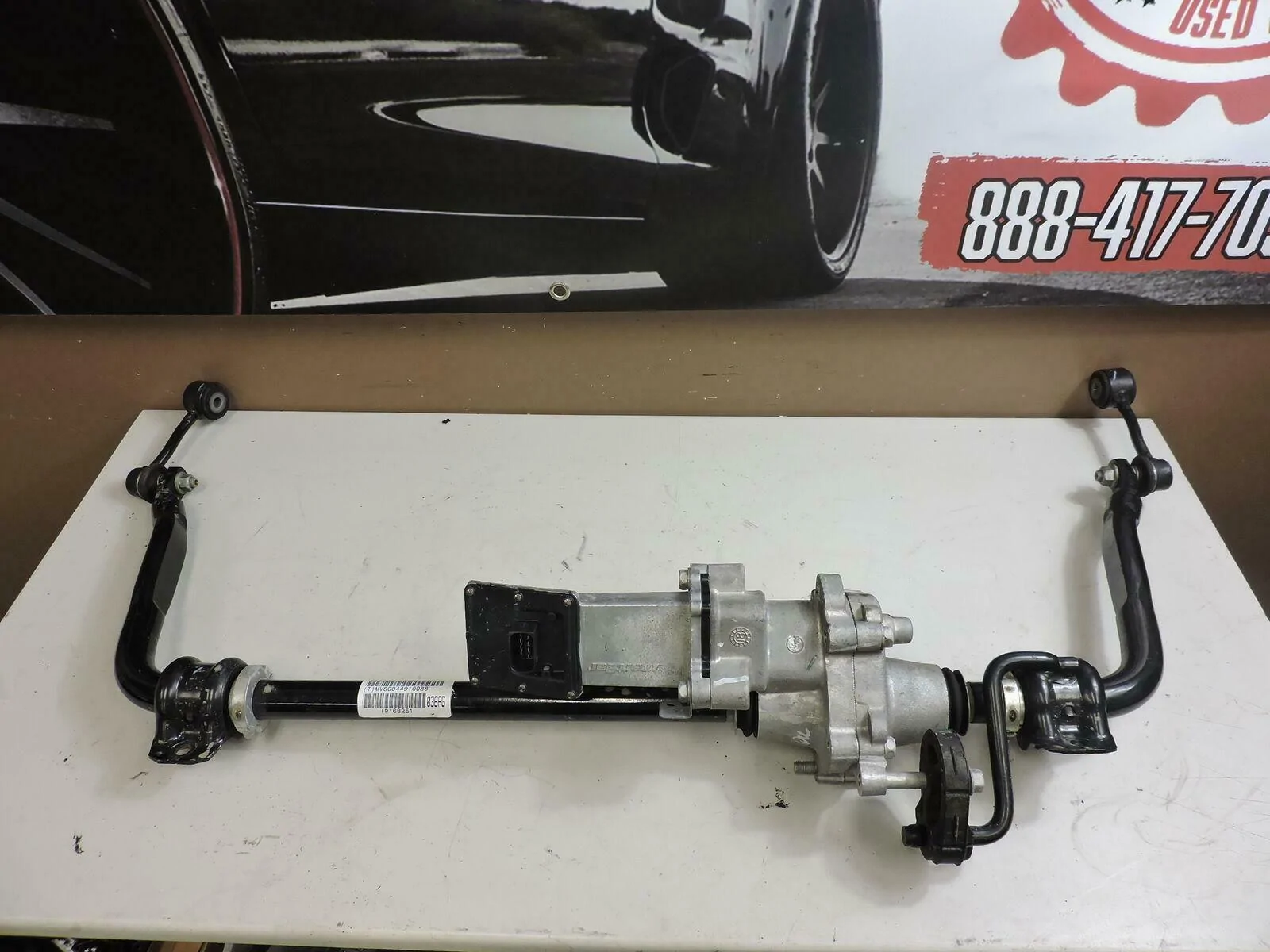
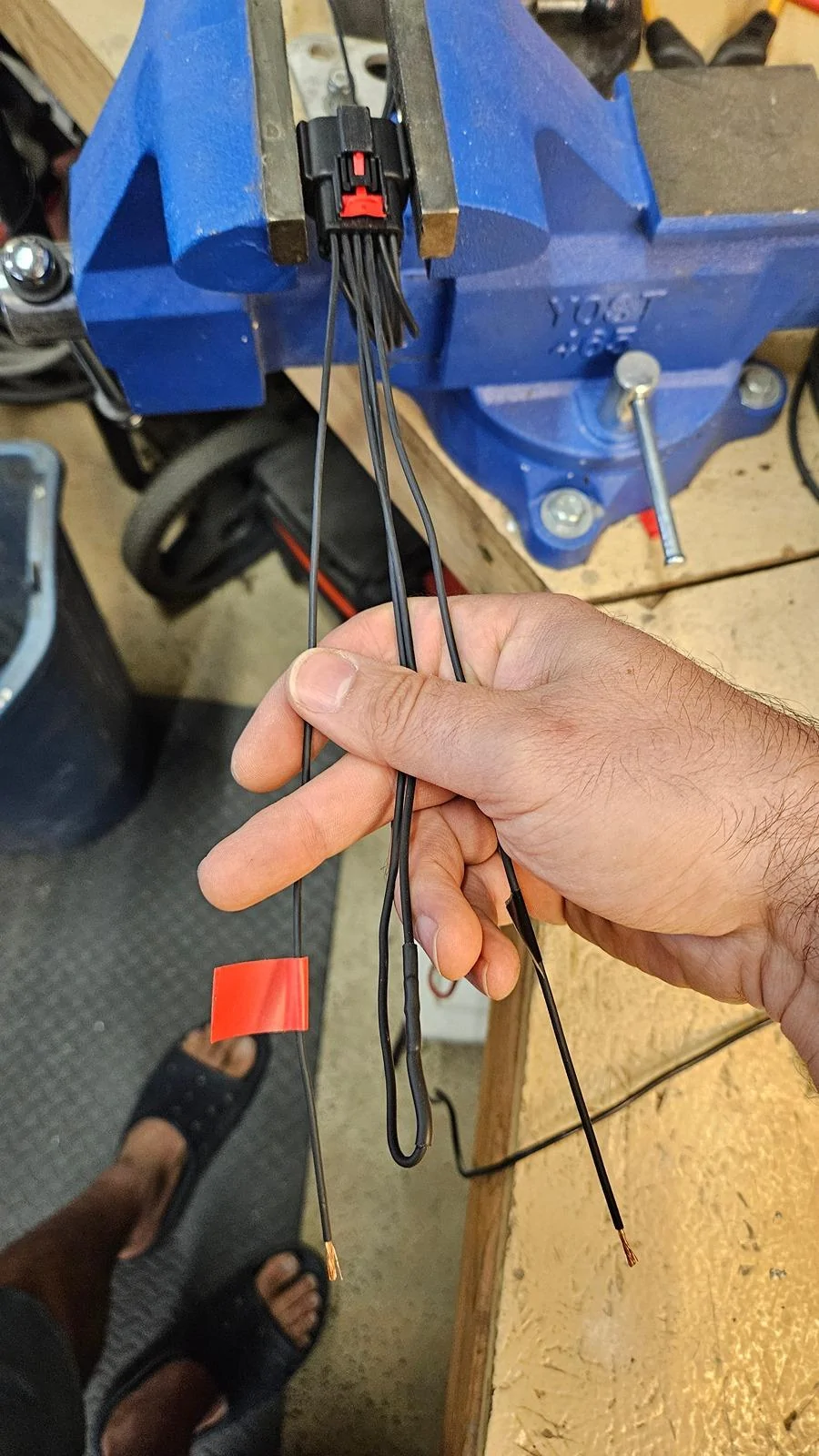
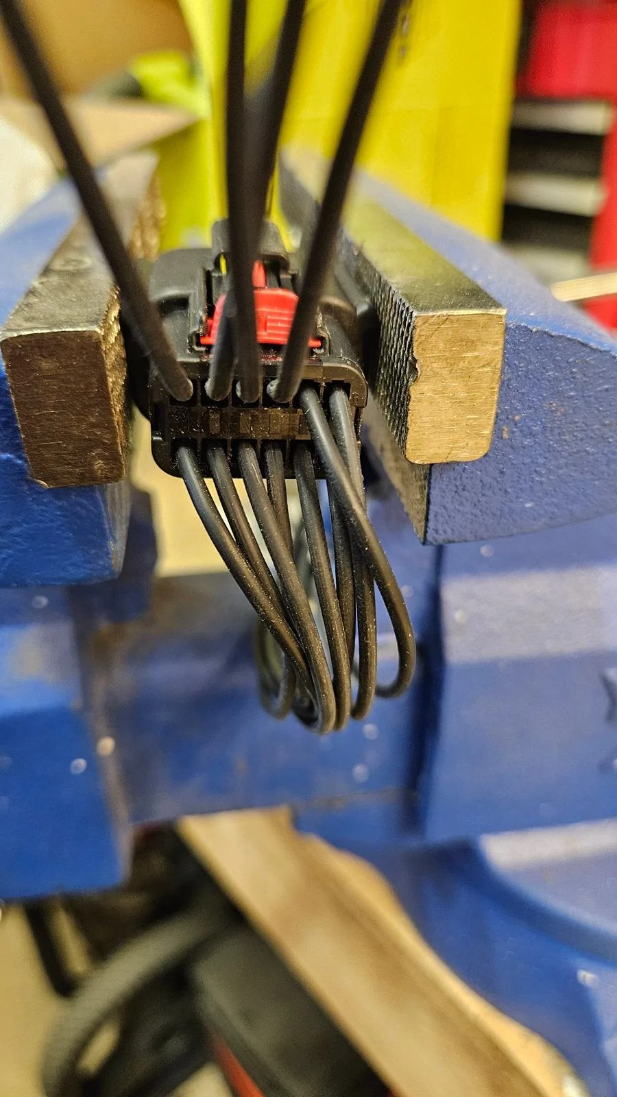
This looks heavy. Does anybody have an idea of how much the SBD weighs over a standard sway bar?I found the July 13th announcements below that show the BWI Group is building the Bronco's Front Stabilizer Bar Disconnect, thanks to a tip from @Aman in another thread that they were the supplier. Below is some of the information on how the unit functions. This unit is only available on the Badlands and First Edition trims, there has been no information to indicate it will be an a la carte option on any other trims. As a reminder, this is a hydraulic system unlike the Jeep Rubicon's electronic sway bar disconnect system.
What are your thoughts, it seems like some very innovative engineering.
BWI Operational Video
BWI product page
BWI Group Front Stabilizer Bar Disconnect announcement 7/13/2020
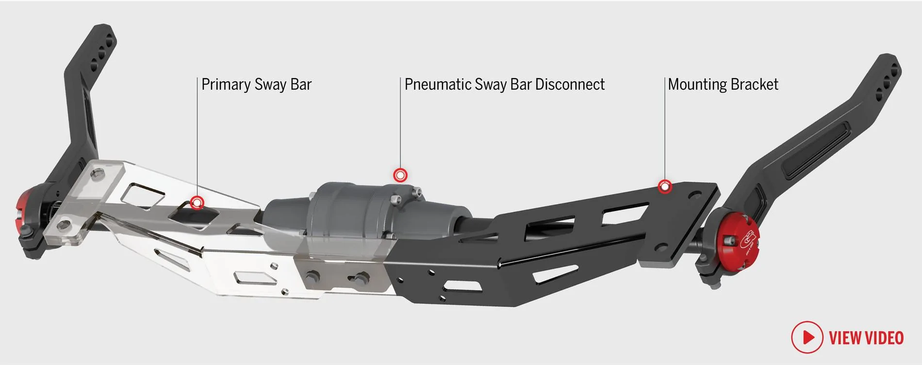
BWI Bronco Front Stabilizer Bar Disconnect
7/13/2020

2021 Ford Bronco
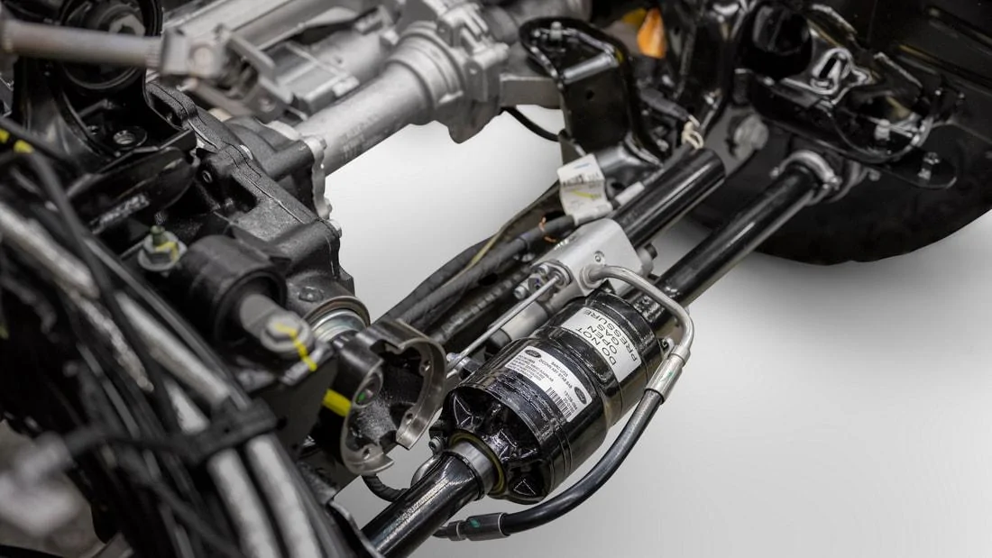
The available front stabilizer bar disconnect off a unique to the segment design for increased articulation across the vehicle to help you up, over and around large obstacles.
BWI Group


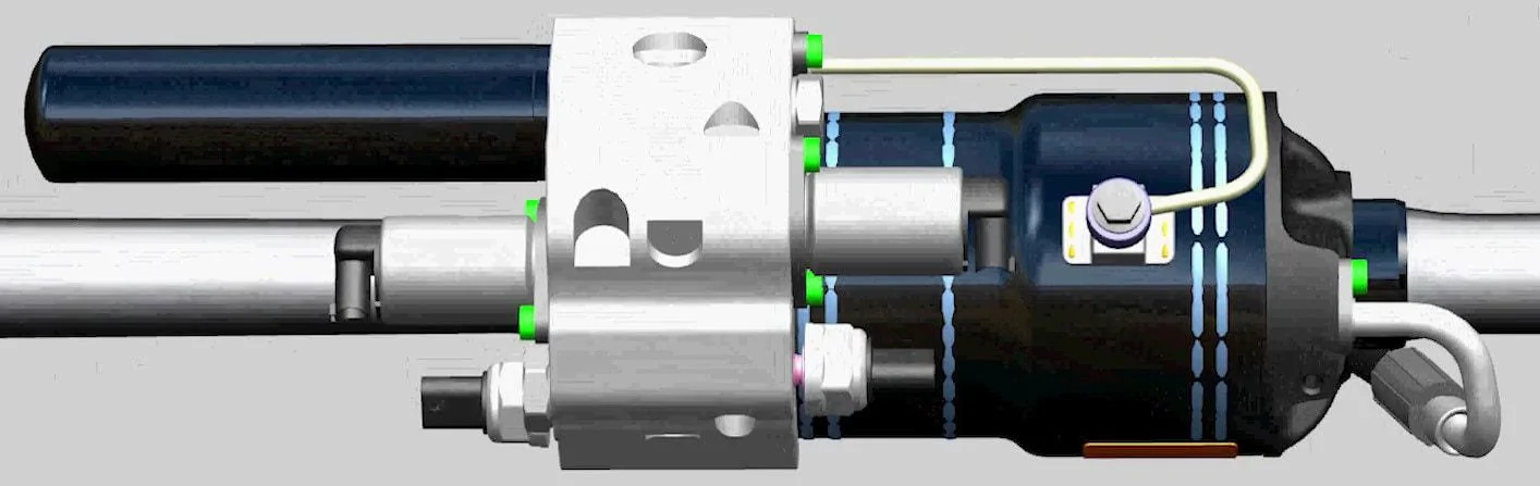
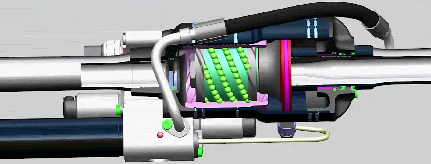
Piston

Stabilizer bar ends are disconnected and free to move on their own.
The solenoid valves are open and the piston (immersed in fluid) is free to move as fluid flushes in and out of the chambers on both sides of the piston.
Full suspension travel is possible. Wheel articulation is not limited by the stabilizer bar.

Stabilizer bar ends are now connected.
Both solenoid valves are closed, preventing fluid flow. The piston is hydraulically locked.
Total suspension roll stiffness is increased and vehicle body roll angle limited while cornering.
BWI Operational Video
.

Sponsored